General principles and features of Maritime Mobile Service
Priorities of communication in the maritime mobile service
Article 53 of the International Telecommunication Union Radio Regulations states that all stations in the Maritime Mobile and the Maritime Mobile-Satellite service shall be capable of offering four levels of priority in the following order:
Distress
A distress message indicates that a mobile unit or person is threatened by grave and imminent danger, and requires immediate assistance.
A distress message has absolute priority over all other communications.
• Distress calls transmitted by radiotelephony are prefixed by the word ‘MAYDAY’ sent three times. Subsequent messages are preceded by the word MAYDAY once only (refer to Section 14.7.2).
Urgency
An urgency message indicates that the calling station has a very urgent message concerning the safety of a mobile unit or person.
An urgency message has priority over all other communications, excepting distress.
Urgency messages transmitted via radiotelephony are prefixed by the words ‘PAN PAN’ sent three times.
Safety
A safety message indicates that the calling station has an important navigational or meteorological warning to transmit.
A safety message has priority over all other communications, excepting distress and urgency.
Safety messages sent via radiotelephony are prefixed by the word ‘SECURITE’ sent three times.
Routine/public correspondence (Other)
A routine message is one not covered by the previous categories. Public Correspondence communications are those which are used to convey routine information between persons on board vessels and those ashore through the public telecommunications network. Examples of Public Correspondence communications are: telephone, fax, email and data messages.
Types of stations in the Maritime Mobile Service
Ship stations
A ship station is a radio station established on board a vessel for communications with stations ashore and other ship stations.
Coastal radio stations
A coast radio station is a radio station established on land for the purpose of communicating with ships at sea.
There are typically two types of coast radio stations:
- Major Coast Station - a station whose major function is the transmission and reception of messages on behalf of the public and also provides GMDSS distress and safety services.
- Limited Coast Station - a station whose major function does not include the handling of messages of a public correspondence nature (see 2.1.4). These stations do not provide GMDSS distress and safety services, and are often operated by volunteer organisations, some State and Territory Government entities and private or commercial entities.
Port operations stations
Port operations stations are established for the operational control of ships in and around ports and harbours. They are also known as “Harbour Control” stations. Some of these stations are classified as Vessel Traffic Service (VTS) stations as defined by the International Maritime Organization (IMO) Resolution A.857(20).
Aircraft stations
Ship stations communicate with aircraft stations during search and rescue operations on designated frequencies.
Rescue Coordination Centre (RCC)
The RCC coordinates search and rescue operations for ships and aircraft and the promulgation of navigation warning information (referred to as Maritime Safety Information - MSI). An RCC is connected by various communications links to coast radio stations, land earth stations and other search and rescue organisations.
Frequencies and Frequency bands
The number of times that the alternating current in a radio wave performs its complete cycle per second is known as its frequency. The international unit of measurement of frequency is the hertz (abbreviated - Hz).
The wavelength of a radio wave is the distance between two successive positive peaks of two cycles. Wavelength is inversely proportional to frequency, i.e. as the frequency of a radio wave increases, the wavelength decreases, and vice-versa.
The wavelength of a radio wave is determined by the formula:
wavelength (m) = velocity in metres (m)s per second (s) divided by frequency in hertz (Hz).
The velocity of a radio wave is a constant 300 000 000 m per second.
Units of frequency
Units of frequency are:
The kilohertz (kHz) = 1 000 hertz
The megahertz (MHz) = 1 000 000 hertz
The gigahertz (GHz) = 1 000 000 000 hertz
Sub-division of the radio frequency spectrum
The radio frequency spectrum is sub-divided into
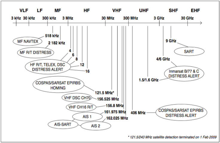
Figure 2 - ITU radio frequency bands and GMDSS usage eight bands, as follows:
Very Low Frequencies (VLF) 3 to 30 kHz
Low Frequencies (LF) 30 to 300 kHz
Medium Frequencies (MF) 300 to 3 000 kHz
High Frequencies (HF) 3 to 30 MHz
Very High Frequencies (VHF) 30 to 300 MHz
Ultra High Frequencies (UHF) 300 to 3 000 MHz
Super High Frequencies (SHF) 3 to 30 GHz
Extra High Frequencies (EHF) 30 to 300 GHz
Frequencies allocated to the Maritime Mobile Service
The International Telecommunication Union (ITU) has allocated various bands of frequencies throughout the radio frequency spectrum to the Maritime Mobile Service and the Maritime Mobile-Satellite Service.
The bands and their uses are detailed in Figure.
Simplex and duplex channels
All HF and all VHF marine frequencies are arranged in a channelised format.
Channels are designated as either:
Simplex – operating method in which transmission is made possible alternatively in each direction of a telecommunication channel, for example, by means of manual (see single frequency); or
Duplex – operating method in which transmission is possible simultaneously in both directions of a telecommunication channel.
Simplex operation
A simplex system allows only one station to transmit at any one time. Communications equipment designed for simplex operation uses one antenna, which is connected to either the transmitter or the receiver through a change-over relay or switch.
Channels used for distress and calling purposes are always operated in simplex mode, so that all stations can hear all others using the frequency.
Duplex operation
Communications equipment designed for duplex operation allows simultaneous transmission and reception on two different frequencies through the use of either two widely spaced antennas or one antenna connected to the transmitter and receiver through special combining and filtering circuitry.
Duplex channels are normally used for public correspondence purposes (i.e. radio telephone calls). Each duplex channel comprises two separate frequencies - one for transmit and one for receive.
Duplex operation allows radiotelephone calls to and from suitably equipped vessels and coast radio stations to be conducted in the same way as telephone calls made over the conventional land telephone system - i.e. both parties can speak and be heard at the same time.
Only two stations can use a duplex channel at any one time.
Semi-duplex operation
Communications equipment that does not have the facility for simultaneous transmission and reception often operates in ‘semi-duplex’ mode - i.e. a method which is simplex operation at one end of the circuit and duplex operation at the other.
HF Radiotelephone Channel Plan
The HF radiotelephone channel plan is described in Appendix 17 of the ITU Radio Regulations, and reproduced in the Manual for use by the Maritime Mobile and Maritime Mobile-Satellite Services (carried by every GMDSS ship).
The plan allocates a series of channels for duplex operation, and a series of channels for simplex (inter- ship) operation. Duplex channels are always referred to by their channel number. This channel number is comprised of 3 or 4 digits, the first one or two representing the frequency band (4, 6, 8, 12, 16, 22 and 26 MHz), and the last two representing the actual channel number, i.e. channel 403 is the third channel in the 4 MHz band, and channel 1602 is the second channel in the 16 MHz band.
Appendix 17 (as per the 2011 edition of the Manual for use by the Maritime Mobile and Maritime Mobile- Satellite Services) lists both the simplex and duplex channels available in the 4 to 26 MHz range. As a result of the introduction of GMDSS, and the move to satellite-based communications methods, these sub-bands have become under-utilized, and with full international agreement, new digital technologies are expected to be introduced into these bands. Each country is allocated a number of channels from each band for use by its coast and ship stations.
VHF radiotelephone channel plan
The VHF channel plan as described in Appendix 18 of the ITU Radio Regulations, and reproduced in the Manual for use by the Maritime Mobile and Maritime Mobile-Satellite Services (carried by every ship using the GMDSS), and is provided in Appendix 10 of the Handbook. The Radio Regulations Appendix 18 was updated at ITU WRC-12, and while the GMDSS channels are unchanged, new single-frequency channels have been created, and more exibility exists for new digital channels, as well as channels for testing of new technologies. Some of these changes will come into e ect from 1 January 2017 and administrations are evaluating how the new channels are to be used locally, and there are some regional variations for the new digital channels. The remarks below refer to the new channel plan.
A total of 68 VHF channels are available in the VHF channel plan. Of these at least 65 are expected to be selectable by the user, but additional channels could be available depending on the manufacturer programming, since a number of channels can be operated in single-frequency or two-frequency mode under various Appendix 18 Notes.
A new channel 2006 has been designated for experimental use for future applications or systems (e.g. new AIS applications, man overboard systems, etc.) – if authorised by administrations. At present, no equipment can monitor this channel, but new equipment may. The eventual usage of this channel in reality is yet to be determined.
Four digit channel numbering
It will be noted that the channel plan now includes four-digit channel numbering for certain channels. Equipment manufacturers are examining how this will be incorporated into their equipment. It is based on Recommendation ITU-R M.1084-4 Annex 4, which adds the “10” pre x to a single-frequency channel number, if a two-frequency channel is operated in single-frequency mode using the ship transmit frequency. Alternatively, the “20” pre x is added to a single-frequency channel number, if a two-frequency channel is operated in single-frequency mode using coast station frequency.
Two channels are exclusively for AIS (AIS 1 and AIS 2) and one is exclusively for DSC (Channel 70). Each simplex and duplex channel is assigned a speci c purpose by the ITU. However while the entire list is contained within the Manual for use by the Maritime Mobile and Maritime Mobile Satellite Services speci cally note the following:
Channel 06: may be employed for communication between ship stations and aircraft stations engaged in co-ordinated SAR operations and ship stations should avoid harmful interference on this channel.
Channel 13: is designated worldwide as a navigation safety communication channel primarily for inter-ship navigation safety communications.
Channel 16: may only be employed for Distress, Urgency, Safety and Calling.
Channels 15 and 17: may be used for on board communications provided the radiated power does not exceed 1 W (low power setting) and such communications are permitted in the waters of the coastal state in which the ship is operating.
Channel 70: is used for Digital Selective Calling for Distress, Safety and calling.
Channels 75 and 76: should be restricted to navigation related communications and as these channels are located in the band either side of channel 16 (see Appendix 10). Measures should be taken to minimize the risk of harmful interference on that channel such as using low power (1 W). At WRC-12, it was agreed that these channels shall also be used to enhance the satellite detection of AIS transmissions from ships. New AIS Class-A and Class-B “SO” transceivers tted with this capability, will automatically transmit a special AIS Message 27 which can be detected by satellite, alternatively on channels 75 and 76 (at 12.5 watts) every 3 minutes, when outside VHF coverage of a terrestrial AIS base station. These transmissions are not expected to cause interference to channel 16.
The frequencies of 161.965 MHz and 162.025 MHz are known as AIS 1 and AIS 2 and are used exclusively for AIS.
Each country determines their own individual channel allocations, based on the ITU guidelines. The band is extensively used by ship, coastal, limited coastal and port operations stations world-wide.
HF Narrow Band Direct Printing (Radio Telex) channel plan
The HF Narrow Band Direct Printing (NBDP - also known as ‘Radio Telex’) channel plan is described in Appendix 17, Section III of the ITU Radio Regulations.
Commercial HF NBDP channels are assigned in a similar fashion to duplex radiotelephone channels. Each channel consists of two frequencies, one for the ship and one for the coast station.
As a result of WRC-12, the Radio Regulations contains two versions of Appendix 17, one which will remain in force until 31 December 2016 and one which will come into force from 1 January 2017. The latter one will have a reduced number of channels available for non- GMDSS NBDP and Morse telegraphy, but an increased number of channels for new digitally-modulated emissions, which also provide for the combining of channels into wider blocks for larger data rates.
While NBDP or TOR (Telex over Radio) has been in sharp decline over a number of years as a commercial service, a new method of text communications has been developed using the same spectrum. This new system which allows the use of e-mail over the terrestrial (HF) bands has been developed as a global network, but does not form part of the GMDSS.
GMDSS distress and safety frequencies
The ITU has allocated simplex (i.e. single frequency) frequencies in the MF, the VHF and each of the HF maritime bands exclusively for distress and safety purposes. These frequencies are protected by international agreement, and any transmission capable of causing harmful interference to distress and safety signals is prohibited.
Component parts of Marine Radio Equipment
The major parts of radio equipment
Marine radio equipment, whether operating in the VHF or MF/HF bands, is made up of three major sections:
- The antenna or aerial;
- The transmitter and the receiver, and
- The power supply. Each part is dependent on the other. A fault in any one of the parts will not allow the equipment to function correctly.
The antenna
The antenna has two functions: • During transmission, to radiate into space the radio frequency energy generated by the transmitter; and • During reception, to gather radio frequency energy from space and pass it to the receiver. The antenna, therefore, is connected to either the transmitter or the receiver, depending whether transmission or reception is taking place.
The changeover is controlled by the ‘press to talk’ switch or button on the microphone or handset. When pressed, the transmitter is turned on and the antenna is connected to it. When released, the transmitter is turned o and the antenna is re-connected to the receiver.
On MF/HF transceivers, to achieve effective communications, it is essential to provide an “earth” to the water surrounding the vessel. Usually, this is achieved by running a heavy at copper strip from the earth terminal of the transceiver to part of the metallic superstructure.
The transmitter and the receiver
The function of the transmitter is to turn voice (audio) or data signals into a form where they can travel over very long distances. This is achieved by converting voice signals spoken into the microphone or data signals presented to the transmitter into high powered radio frequency energy which is passed to the antenna and radiated as ground and sky waves.
The function of the receiver is to select only those radio frequency signals which are required by the operator and amplify them. These signals are then converted back into voice or data signals and reproduced by a loudspeaker or fed to a data device.
It is usual with marine radio equipment for the transmitter and receiver to be combined in a single unit called a transceiver.
The power supply
The function of the power supply is to supply electrical energy to the transmitter and the receiver to enable them to carry out their tasks.
Fuses located in the wiring between the power supply and the transceiver protect the equipment against damage should a malfunction occur.
Modes of communications
Marine radio equipment uses various modes of emission for di erent functions. These modes can be summarised as follows:
radiotelephone - the most common mode of operation. In this mode, voice signals are transmitted over a radio link using various forms of modulation (see below).
Narrow band Direct printing (NbDp) - telex signals are transmitted over radio.
Digital Selective Calling (DSC) - A paging system that uses data signals to automate the transmission of distress, urgency or safety calls via MF, HF or VHF radio.
As outlined in Section 2.4.6, the ITU has allocated a speci c frequency in the MF, each of the HF and the VHF marine bands for distress and safety tra c via each of these three modes of operation.
Radiotelephone
In this system, at the transmitter, audio (voice) signals are modulated (or combined) with a radio frequency signal - referred to as a carrier. In the receiver, these signals are de-modulated, the audio is separated from the radio carrier, ampli ed and passed to the loudspeaker.
There are two main types of modulation used in Maritime Mobile radiotelephone transmissions -
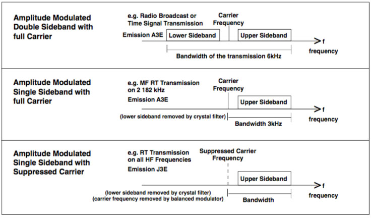
Amplitude Modulation (AM) is the method of modulation used on all MF and HF Maritime Mobile Bands. In this system the amplitude of the radio frequency carrier is modulated or varied by the audiosignal. This type of modulation produces a radio frequency carrier and two ‘sidebands’ which contain the audio information. It is sometimes referred to as ‘Double Sideband’.
This system is used by broadcasting stations, such as commercial and ABC radio stations.
Single Side band, suppressed carrier. The two sidebands in the double sideband system described previously each contain identical audio information. Single Side Band, suppressed carrier equipment contains special filters that completely remove the radio carrier and one of the sidebands from a double sideband signal. This allows a great increase in efficiency, as all the radio frequency power is concentrated in one sideband only - either the Lower Side Band (LSB) or the Upper Side Band (USB). SSB receivers automatically re-insert the carrier, and de-modulate the audio signals in the same way as a double sideband AM (A3E) receiver.
Single Side Band, suppressed carrier (J3E) operation is mandatory on all maritime MF and HF radiotelephone channels, apart from 2 182 kHz. The Upper Side Band (USB) mode of operation is used. Some equipment does provide facilities to enable selection of the Lower Side Band (LSB) mode of operation - this must not be used.
Single Side band full carrier. Under the ITU Radio Regulations this mode is only permitted on the MF International Distress frequency of 2 182 kHz. This mode is known as “compatible AM” or H3E.
Because of its full carrier, Double Side Band receivers are able to receive these signals. Although the H3E emission mode has been phased out, some ships and coast stations continue to use SSB full carrier (H3E) on 2 182 kHz. However radiotelephone communications, including distress traffic, on 2 182 kHz should be conducted on SSB suppressed carrier emission (J3E). (Further information is available in ITU 2012 Radio Regulations Appendix 15.)
The various forms of amplitude modulation are shown in Figure.
Frequency Modulation (FM) - in this system the frequency of the radio frequency carrier is modulated or varied by the audio signal. As FM produces high quality sound, given su cient bandwidth, it is used in television and radio broadcasting (e.g. FM stereo).
FM is not used on marine MF or HF frequencies. A close variant of FM, called Phase Modulation (PM), is used exclusively on the VHF marine band.
Digital Selective Calling (DSC)
DSC is a paging technique used to automate the initial call between two stations. The technical principles are almost identical to NBDP, in that tone information is transmitted from one DSC system to another over a radio link.
DSC is used in the MF, HF and VHF marine bands for distress, urgency and safety alerting.
VHF DSC systems operate at far greater speed than MF or HF systems - 1 200 bits of information per second on VHF, 100 bits of information per second on MF/HF.
Bandwidth of emissions
The bandwidth of a signal is the amount of Radio Frequency spectrum occupied by that signal. Different modulation methods produce different bandwidths. Typical bandwidths for the various forms of modulation in maritime are:
FM – up to 10 kHz (however signals of up to 16 kHz may be accommodated)
AM – 3 kHz
SSB – up to 3 kHz
NBDP and DSC – 170 Hz
Classification and designation of emissions
Appendix 1 of the ITU Radio Regulations establishes a system of identifying radio emissions by designating the bandwidth and classifying the characteristics of the emission. As such an emission can be identi ed in terms of:
- The bandwidth allocated;
- The characteristics of the modulation and the modulating signal; and
- Any additional characteristics.
A total of nine letters and figures can be used to classify a radio emission, the first four indicating the bandwidth, and the next three the modulation characteristics. The last two characters are optional and may be used to identify the details of the signal and the nature of multiplexing where appropriate. The first two groups of characters are of greatest relevance to the GMDSS, an example of how these groups are employed is demonstrated below: From the emission classified as:
2K80J3E
The first four characters (2K80) designate a bandwidth of 2.8 kHz.
Classification
The next three characters give the:
- Type of Modulation of the main carrier;
- Nature of signal modulating the main carrier; and
- The type of information to be transmitted.
For the example J3E this corresponds to:
J = single sideband, suppressed carrier
3 = single channel containing analogue information
E = telephony
The following simplified designators are commonly used in the GMDSS:
J3E = Single sideband (SSB)
F3E = Frequency modulation (FM)
G3E = Phase modulation used on VHF
F1B or J2B = Narrow Band Direct Printing (NBDP) or Digital Selective Calling (DSC)
F3C = Facsimile (Fax)
A complete list of emission designators may be found in the Manual for use by the Maritime Mobile and Maritime Mobile - Satellite Services (detailed in Appendix 1, Section II). This publication is carried by all GMDSS vessels.


"Thanks for sharing such an amazing blog.
I have learnt alot from it.
For more information visit https://www.mvvsmaritime.com/"